Detailed schematics of
mobile phone charger
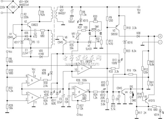 The charger uses the RCC -type switching power supply, ie the oscillation suppression converter , PWM switching power supply it with a certain distinction. PWM Type Switching Power Supply by independent sampling error amplifier and DC amplifier pulse width modulation system ; while RCC -type switching power regulator is composed only by the level switch , status and control process for the oscillation suppression status . Since the PWM switching power supply in the switch -off is always periodic system control just changing the pulse width of each cycle , the RCC type switching power supply control process and a continuous linear variation , it has only two states: when the switching power supply output voltage exceeds the rated value, the pulse controller output low, cut-off switch ; when switching power supply output voltage is below the rated value, pulse controller output high , the switch is turned on. When the load current decreases, the filter capacitor discharge time is extended , the output voltage will not soon be reduced , the switch is off, until the output voltage drops below the rated value , the switch will be turned on again . The deadline switch depends on the load current. Switch on / off by the switch from the output voltage level of the control sample . So this power supply , also known as non-periodic switching power supply.
220V electricity through VD1 ~ VD4 bridge rectifier after forming a collector of V2 DC voltage of about 300V . V2 and composed by a blocking oscillator switching transformer . After power on , 300V DC voltage V2 is applied through the transformer primary collector , while the voltage is also through the startup resistor R2 is V2, a base bias voltage. Due to the positive feedback effect , V2 Ic rising quickly saturated , at V2 into OFF , the switch transformer secondary winding of the induced voltage to VD7 conduction, to the load to output a DC voltage of about 9V . Switching transformer feedback winding the induced pulse rectified by VD5 , C1 filtered to produce a number of pulses with the oscillation is proportional DC voltage. If this voltage exceeds the value of the regulator regulator VD17 , VD17 will turn this negative rectified voltage V2 will be added to the base , it quickly closed. V2 deadline is inversely proportional to its output voltage . VD17 on / off directly by the mains voltage and load. The lower the grid voltage or the load current increases , VD17 shorter conduction time , V2 longer conduction time , on the contrary , the higher the grid voltage or load current is smaller , VD5 rectified voltage is higher , VD17 conduction time the longer , V2 shorter conduction time . V1 is the overcurrent protection tube , R5 is V2 Ie sampling resistor. When V2 Ie is too large , R5 voltage drop across the conduction V1 , V2 closed, can effectively eliminate the impact of current instant boot , while VD17 control function is also a kind of compensation . VD17 sampling the voltage V2 to control the oscillation time, and V1 V2 is to control the oscillation current sampling time .
If it was for nickel- cadmium, nickel-metal hydride battery, because there is a certain type of battery memory effect , need to be discharged from time to time . SW1 is a nickel -cadmium , nickel metal hydride, lithium ion battery switch. SW1 and Precision Reference Supply SL431 offers the op amp LM324 ⑨ two different precision reference source of the SW1 switch . In a nickel- cadmium, nickel-metal hydride battery is charging , LM324 ⑨ pin reference voltage of about 0. 09V ( no load ) ; in a lithium-ion battery charging , LM324 ⑨ pin reference voltage is approximately 0. 08V ( no load ) , this designed by these two types of battery characteristic chemical characteristics of the decision . Press SW2, V5 base instantly get a low and conduction, the residual voltage rechargeable Ikegami 's ec through V5 R17 on pole at discharge , and discharge lamp VD14 lit. SW2 is pressed immediately after the release , when the residual voltage of the rechargeable Ikegami by R16, R13 divider , C9 V4 after filtering to provide a high level to the base , V4 conduction, which is equivalent to short-circuit SW2. As the discharge time, the residual voltage of the rechargeable Ikegami more low , when the voltage V4 on the base can not be maintained when it continues to conduct , V4 end, the discharge end , the charger then transferred to the state of charge .
Since there is no memory effect of lithium when the battery is less than 3V when they can not boot, the residual voltage through the resistor R40, R41 partial pressure obtained after 2. 53V into the op amp inverting input ③, ⑤, ⑩ feet, foot voltage due LM324 ⑨ under load is always 2. 66V, so ⑧ pin output low , V3 conduction , +9 V voltage through V3 ec pole , VD8 to rechargeable batteries. IC1 d under the action of the capacitor C6 , { 14} pin output is a pulse signal , since IC1 ⑧ pin is low , so VD12 is flashing to indicate the battery is charging , corresponding to a capacity of 20%. As the charging time, the rechargeable Ikegami voltage is gradually increased . When R40, R41 partial pressure value is approximately equal to 2. 58V , that IC1 ③ feet equal to 2. 58V when , IC1 ② feet by the resistor divider after that 2. 57V, its ① pin output high ( due to the charge , IC1 ⑨ pin voltage is always 2. 66V, V6 conduction; Conversely, when the no-load , IC1 ⑨ feet to 0. 08V, V6 off ), VD10, VD11 lit, the corresponding indicator capacity of 40 %, 60% . When R40, R41 partial pressure values of up to 2. 63V , that IC1 ⑤ feet equal to 2. 63V, its ⑥ feet by the resistor divider after that 2. 63V, ⑦ pin output high , VD9 light , corresponding to the charge capacity is 80%. Only IC1 ⑩ pin voltage is ≥ 2. 66V when , ⑧ feet only output high , VD13 lit, corresponding to 100% charge capacity . Even VD13 lit , VD12 is still flashing , it indicates that the battery has not yet reached full saturation . Only IC1 ⑧ pin voltage > 6. 5V when , VD12 gradually extinguished , which means that the battery is fully charged to saturation .
VD16 in the circuit from over-charging , over-current protection function , VD8 protection from reverse to avoid the charger power off, reverse battery discharge .
The charger uses the RCC -type switching power supply, ie the oscillation suppression converter , PWM switching power supply it with a certain distinction. PWM Type Switching Power Supply by independent sampling error amplifier and DC amplifier pulse width modulation system ; while RCC -type switching power regulator is composed only by the level switch , status and control process for the oscillation suppression status . Since the PWM switching power supply in the switch -off is always periodic system control just changing the pulse width of each cycle , the RCC type switching power supply control process and a continuous linear variation , it has only two states: when the switching power supply output voltage exceeds the rated value, the pulse controller output low, cut-off switch ; when switching power supply output voltage is below the rated value, pulse controller output high , the switch is turned on. When the load current decreases, the filter capacitor discharge time is extended , the output voltage will not soon be reduced , the switch is off, until the output voltage drops below the rated value , the switch will be turned on again . The deadline switch depends on the load current. Switch on / off by the switch from the output voltage level of the control sample . So this power supply , also known as non-periodic switching power supply.
220V electricity through VD1 ~ VD4 bridge rectifier after forming a collector of V2 DC voltage of about 300V . V2 and composed by a blocking oscillator switching transformer . After power on , 300V DC voltage V2 is applied through the transformer primary collector , while the voltage is also through the startup resistor R2 is V2, a base bias voltage. Due to the positive feedback effect , V2 Ic rising quickly saturated , at V2 into OFF , the switch transformer secondary winding of the induced voltage to VD7 conduction, to the load to output a DC voltage of about 9V . Switching transformer feedback winding the induced pulse rectified by VD5 , C1 filtered to produce a number of pulses with the oscillation is proportional DC voltage. If this voltage exceeds the value of the regulator regulator VD17 , VD17 will turn this negative rectified voltage V2 will be added to the base , it quickly closed. V2 deadline is inversely proportional to its output voltage . VD17 on / off directly by the mains voltage and load. The lower the grid voltage or the load current increases , VD17 shorter conduction time , V2 longer conduction time , on the contrary , the higher the grid voltage or load current is smaller , VD5 rectified voltage is higher , VD17 conduction time the longer , V2 shorter conduction time . V1 is the overcurrent protection tube , R5 is V2 Ie sampling resistor. When V2 Ie is too large , R5 voltage drop across the conduction V1 , V2 closed, can effectively eliminate the impact of current instant boot , while VD17 control function is also a kind of compensation . VD17 sampling the voltage V2 to control the oscillation time, and V1 V2 is to control the oscillation current sampling time .
If it was for nickel- cadmium, nickel-metal hydride battery, because there is a certain type of battery memory effect , need to be discharged from time to time . SW1 is a nickel -cadmium , nickel metal hydride, lithium ion battery switch. SW1 and Precision Reference Supply SL431 offers the op amp LM324 ⑨ two different precision reference source of the SW1 switch . In a nickel- cadmium, nickel-metal hydride battery is charging , LM324 ⑨ pin reference voltage of about 0. 09V ( no load ) ; in a lithium-ion battery charging , LM324 ⑨ pin reference voltage is approximately 0. 08V ( no load ) , this designed by these two types of battery characteristic chemical characteristics of the decision . Press SW2, V5 base instantly get a low and conduction, the residual voltage rechargeable Ikegami 's ec through V5 R17 on pole at discharge , and discharge lamp VD14 lit. SW2 is pressed immediately after the release , when the residual voltage of the rechargeable Ikegami by R16, R13 divider , C9 V4 after filtering to provide a high level to the base , V4 conduction, which is equivalent to short-circuit SW2. As the discharge time, the residual voltage of the rechargeable Ikegami more low , when the voltage V4 on the base can not be maintained when it continues to conduct , V4 end, the discharge end , the charger then transferred to the state of charge .
Since there is no memory effect of lithium when the battery is less than 3V when they can not boot, the residual voltage through the resistor R40, R41 partial pressure obtained after 2. 53V into the op amp inverting input ③, ⑤, ⑩ feet, foot voltage due LM324 ⑨ under load is always 2. 66V, so ⑧ pin output low , V3 conduction , +9 V voltage through V3 ec pole , VD8 to rechargeable batteries. IC1 d under the action of the capacitor C6 , { 14} pin output is a pulse signal , since IC1 ⑧ pin is low , so VD12 is flashing to indicate the battery is charging , corresponding to a capacity of 20%. As the charging time, the rechargeable Ikegami voltage is gradually increased . When R40, R41 partial pressure value is approximately equal to 2. 58V , that IC1 ③ feet equal to 2. 58V when , IC1 ② feet by the resistor divider after that 2. 57V, its ① pin output high ( due to the charge , IC1 ⑨ pin voltage is always 2. 66V, V6 conduction; Conversely, when the no-load , IC1 ⑨ feet to 0. 08V, V6 off ), VD10, VD11 lit, the corresponding indicator capacity of 40 %, 60% . When R40, R41 partial pressure values of up to 2. 63V , that IC1 ⑤ feet equal to 2. 63V, its ⑥ feet by the resistor divider after that 2. 63V, ⑦ pin output high , VD9 light , corresponding to the charge capacity is 80%. Only IC1 ⑩ pin voltage is ≥ 2. 66V when , ⑧ feet only output high , VD13 lit, corresponding to 100% charge capacity . Even VD13 lit , VD12 is still flashing , it indicates that the battery has not yet reached full saturation . Only IC1 ⑧ pin voltage > 6. 5V when , VD12 gradually extinguished , which means that the battery is fully charged to saturation .
VD16 in the circuit from over-charging , over-current protection function , VD8 protection from reverse to avoid the charger power off, reverse battery discharge .
Micro power electronics (HK) co.,limited is a professional power supply desiger and manufacturer. If you have any questions or demand about power supply, pls feel freely to contact us. We will try our best for you.

 Request A Quote